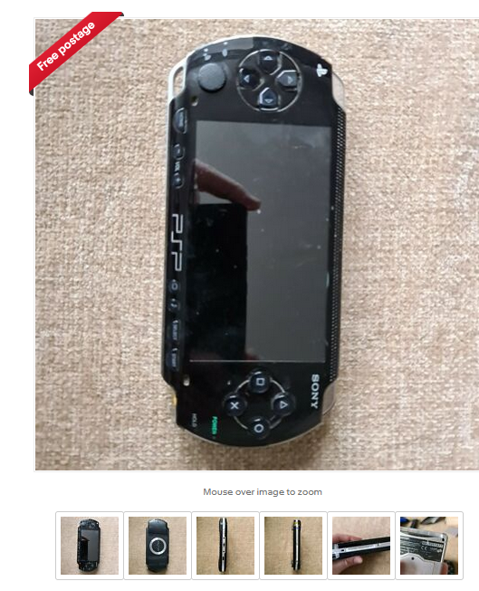
A few days ago while browsing ebay someone had just listed a faulty Sony PSP for the low price of £20. I’m not too interested in PSPs ate this time but looking through the photos of the item, and something caught my eye.
The last photo for the PSP actually showed the back of a Gameboy SP, with the PSP in the background. This gave me a good idea that the very next thing they were going to list was that Gameboy.
The missing Gameboy
A few minutes later and lots of F5’ing, sure enough they listed a silver GBA SP with a buy it now price. Thankfully my immediate offer was quickly accepted and I am now the new owner of a silver GBA SP.
Good cleaning and free gaming
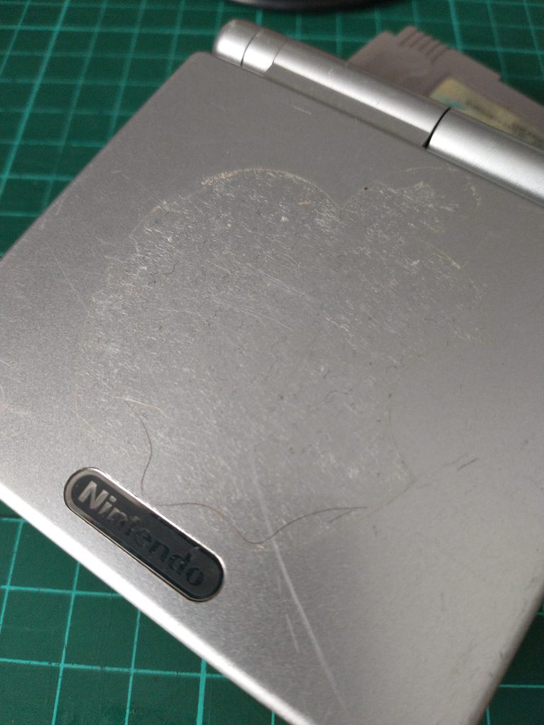
There was some cleaning to do when it arrived, a previous owner had customised it with an Apple logo sticker on the top of the case which left a lot of glue to remove but the seller did send out a game with it too, which I wasn’t expecting.
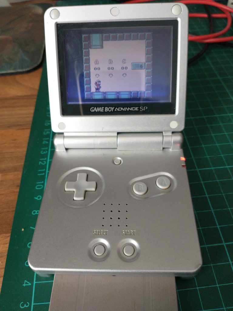
After a good clean with Mr Sheen (don’t use alcohol on plastics), here it is tested and working. Although being sold as faulty, it does power on, play the included game, Super Mario Land 2: 6 Golden Coins and the charging light illuminates when connected to the mains.
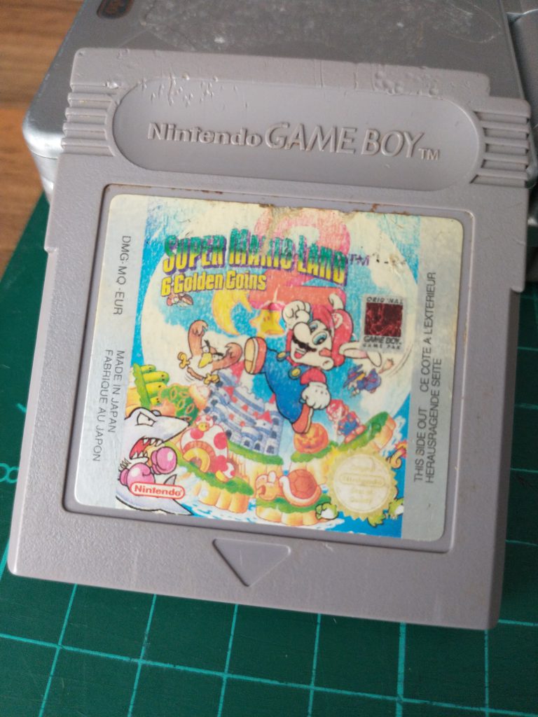
The game cartridge has seen better days, you can tell someone has enjoyed playing this game a lot. It’s not the correct format for the SP but it is my first gameboy game cartridge, which I will be keep for testing gameboys I own in the future.
Happy ebay hunting guys
So I am of course very happy with my purchase. It goes to show it’s worth browsing people’s listing and having a good virtual rummage if you have the time.
It’s going to hard to find a better bargain in the future.
During February 2021 I have been buying and selling a few games consoles, with the goal of making enough profit to buy myself a hot air re-work station and then hopefully an oscilloscope.
Handheld devices are new to me, as I have never owned a Gameboy, DSI or similar, but I know they are still very popular.
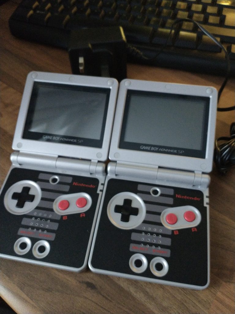
So I took a chance and picked up these two Gameboy Advance SP NES edition, the pair were being sold as ‘faulty batteries, won’t turn on’, and I paid £50 for them delivered.
When they arrived, I was pleased to see they were in good condition and the housing was original too. It wasn’t until I paid the money, did I learn there were reproduction ones being sold too.
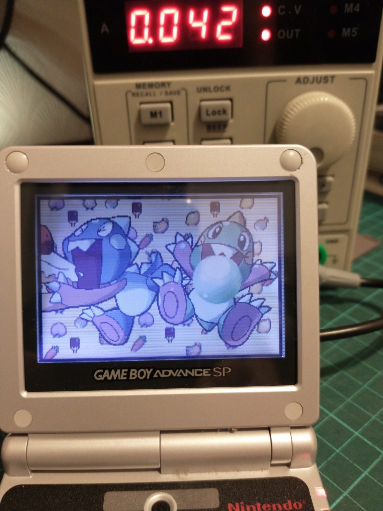
Supplying power through the bench top PSU
My first step was to remove one of the batteries and hook up my bench top PSU to the battery terminals on the GBA, carefully dialling in the correct voltage and amps from information on the battery.
The GBA turned on and was games loaded without any issue. Sound was also working, I will come back to that later.
Battery Charging with the TP4056
Using the TP4056 li-on charging board and an USB volt/amp meter tester, I could see the battery was charging. Both consoles turned on and played games from the charged battery.
Testing the charger
So both Gameboys work with a charged battery, but the charger won’t charge the battery. So I’m beginning to think there is a charge problem inside the GBAs, but it’s unlikely both would suffer the same fate.
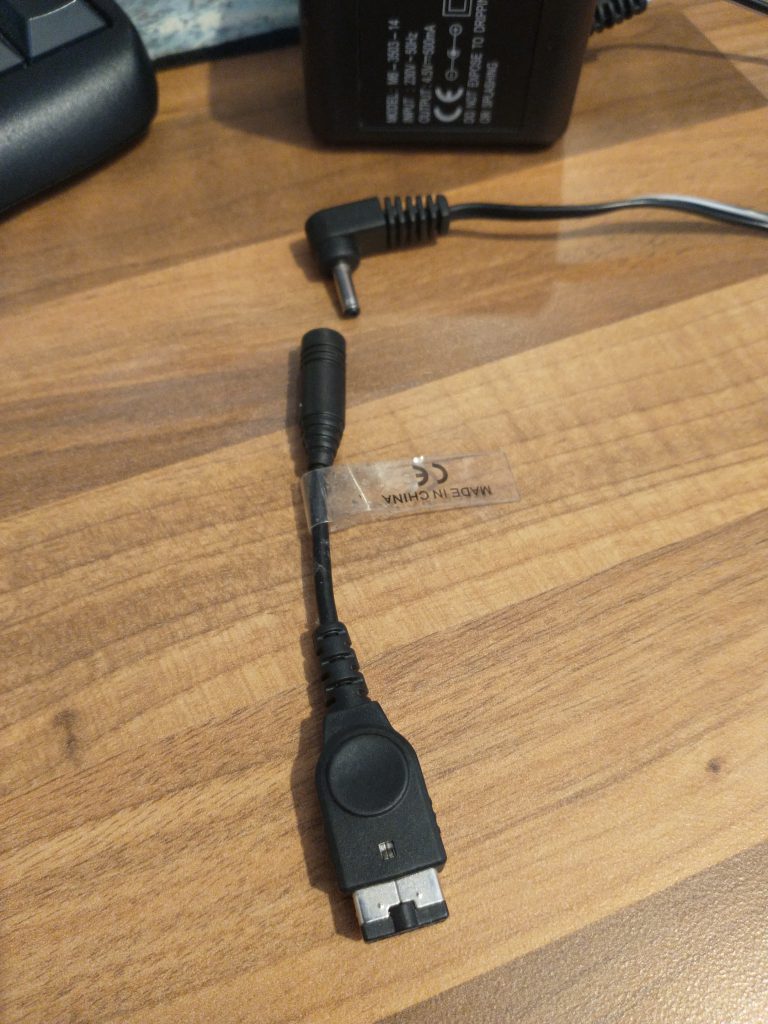
If you know about GBA SPs you might have already figured out what’s wrong with the above photo.
I snipped the jack plu off the charger the ebay seller provided, plugged it back into the above adapter and powered the GBA using my bench top PSU.
The penny dropped
Two things seemd odd. 1. The GBA didn’t take any amps from the bench top PSU (which meant only the battery was providing power). and 2. There was no sound coming from the speaker.
After some research I learnt the adapter in the above photo, is not a power adapter, it’s for headphones. The previous owner had been trying to power both GBAs through the headphone adapter.
Thankfully no harm seems to have been done to the consoles. There is a new charging cable on the way and it seems I have been lucky with these two.
A lot of time could have been saved, if I had a proper charger and not relied on what the seller provided but with the help of the TP4056, USB meter and bench top PSU it all worked out in the end.
I’ll test these properly and sell them on the add to my hot air re-work station fund.
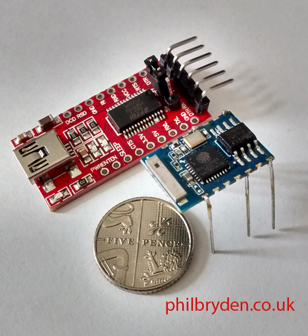
This post is for the compete beginner with an interest in the ESP8266 microcontroller. Specifically the plain standard board ESP8266-03.
TTL USB adapter with standard ESP8266-03. Legs have been soldered on, to attach the microcontroller to a breadboard. These things are tiny, much smaller than I expected.
Let’s start with a disclaimer. I’m a completer beginner too. I have no microcontroller experience, never owned an Arduino, or used any kind of development board in the past. So, don’t take this post as an how-to guide, as I may not be following ‘best practises’. I provide this information as I have done it, and take no responsibility if something goes wrong.
What I’ll cover today, and what I won’t
I won’t cover what the board can do, I will assume you have already done your homework and decided you want to get the board set up and programmed with something simple to get started.
Here are steps this post will cover.
Set up the correct wires on a TTL USB adapter.
Solder some pins onto the ESP8266-03 connectors which will allow it to be plugged into a breadboard.
Install a push button switch on the breadboard (allows the ESP8266-03 to start up in program mode later).
Install an LED and 1K resistor on pin GPIO 12.
Set up Arduino IDE and install the ESP8266 board manager.
Boot the ESP8266-03 in program mode, load the sketch, reboot the ESP in normal mode to run the sketch.
On the software side we will use the Arduino IDE (which is free), to send a program (Arduino calls them ‘sketches’ to the board), which will flash the LED and display text to the serial console in the Arduino IDE.
Step One: Set up the correct wires on a TTL USB adapter.
Make sure it has: RX, TX, 3.3V out and GND. These are the pins we’ll be connecting to the ESP8266-03 module and the breadboard.
I soldered four wires to the pins RX, TX, 3.3v VCC and GND. The soldered connectors are prevented from shorting between each other with some (poorly applied) heat-shrink tubing. RX goes to TXD, TX goes RXD on the ESP8266 and I connected the 3.3v and GND to the power rails on the side of the breadboard.
Step Two. Solder some pins onto the ESP8266-03 connectors which will allow it to be plugged into a breadboard.
Identify the input / output / power connectors needed and solder on some connector pins. If you aren’t using a breadboard perhaps you can just solder on some fine wires. I found some connector pins on an old DVD circuit board, but you could probably cut some legs from a few LEDs.
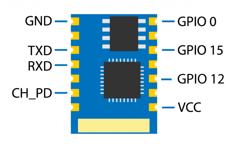
These are the pins we will be using to set up the EPS8266-03
GND goes to ‘-‘ on the breadboard TXD goes to the RX pin on the TTL USB adapter RXD goes to the TX pin on the TTL USB adapter CH-PD goes to ‘+’ on the breadboard GPIO 0 goes to a push button, which goes to ‘-‘ on the breadboard GPIO 12 goes to an LED to 1K resistor, which goes to ‘-‘ on the breadboard GPIO 15 goes to ‘-‘ on the breadboard VCC goes to ‘+’ on the breadboard
Step Three. Install a push button switch on the breadboard
Now this is where I initially had trouble. To be able to send sketches from the Arduino IDE, you have to boot the ESP8266 into program mode. You do this by shorting pin GPIO 0 to ground while powering it up. I’ve used a push button on my breadboard, but you can leave it off and just use a simple jumper wire from the pin to the ‘-‘ rail on the breadboard.
So when i want to load a new sketch, with the board off, I hold down the push button (which shorts pin GPIO 0 to GND), then plug in the USB cable, wait a moment and release the push button. The board is now in program mode. I can load the sketch using the Arduino IDE.
When the sketch has been installed, I pull out the USB cable to remove power. Then plug the USB cable back in, to switch the board back on, into normal mode, and the sketch will start running automatically.
Step Four. Install an LED and 1K resistor on pin GPIO 12.
To see the output connect an LED to GPIO12, then use a 1K resistor to GND. The code in the sketch will turn on the LED and read the status of GPIO 12 and print the output to the Arduino IDE serial monitor.
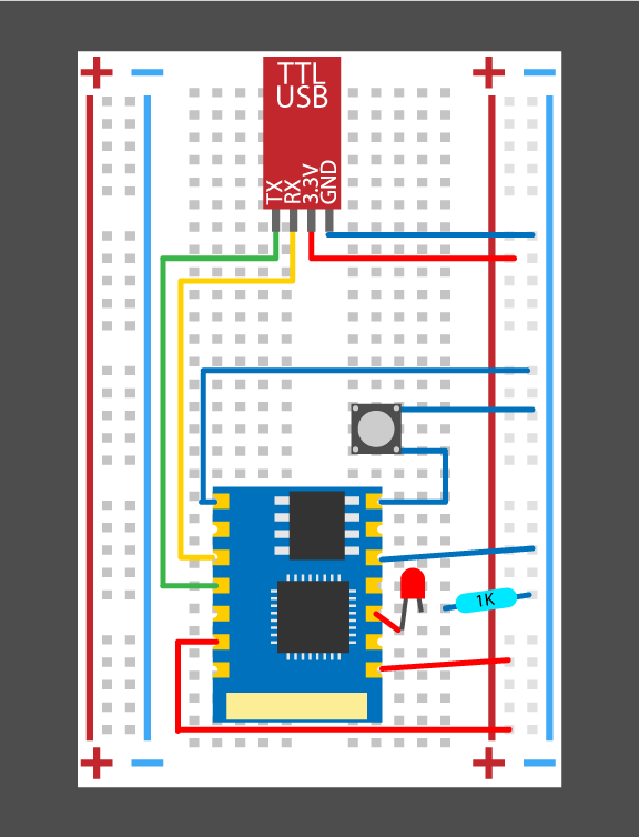
Here is a plan of the layout.
Notice TX goes to RX and RX goes to TX. The pushbutton connects to GPIO 0 (for booting the board into Program mode). The LED is on pin GPIO 12, then to GND through a 1K resistor.
Step Five. Set up Arduino IDE and install the ESP2866 board manager.
Head to Tools/Boards manager and search for 8266, and install the ESP8266 by ESP8266 Community. From the list of boards you should now select ‘Generic ESP8266 Module’.
Step Six. Boot the ESP8266-03 in program mode, load the sketch, reboot the ESP8266-03 in normal mode to run the sketch.
Blink is basic sketch that comes with the Arduino IDE. The original version of the ESP8266 had a built in blue LED. Because we’re using version 3, there’s no LED, so I have wrote my own code to use GPIO 12 instead.
/*
  Turns an LED connected to GPIO12 on for one second, then off for one second, repeatedly.

  Reads the status of pin GPIO12 and outputs status to the Serial Monitor.

  This code is inspired by the BLINK sketch which is unsuitable for ESP8266-03 because it lack a built in LED.

  by Phil Bryden

  http://www.philbryden.co.uk
*/

// the setup function runs once when you press reset or power the board
void setup() {

  pinMode(12, OUTPUT);  // initialize digital pin GPIO12 as an output.
  Serial.begin(115200); // initialize serial monitor.
}

// the loop function runs over and over again forever
void loop() {

  digitalWrite(12, HIGH);              // turn the LED on (HIGH is the voltage level)
  Serial.println(digitalRead(12));     // Reads the out put of GPIO12 and displays it in the serial monitor
  delay(1000);                       // wait for a second


  digitalWrite(12, LOW);             // turn the LED off by making the voltage LOW
  Serial.println(digitalRead(12));   //Reads the out put of GPIO12 and displays it in the serial monitor
  delay(1000);                      // wait for a second
}
To install this code
Paste the code above into a new sketch in the Arduino IDE Hold the push button down, while plugging in the USB Release the pushbutton (the board is in program mode) Click the upload arrow icon (top left) in Arduino IDE Wait for the code to be installed (mine displays ‘Hard resetting via the RTS pin…’ when done) Unplug and plug in the the USB cable (without holding the push button down) to restart the ESP8266-03 The board should now be in normal mode and the code will run automatically.
If all has gone well the LED will blink on and off for 1 second. There should also a print of what is happening in the Tools/ Serial Monitor window, 1 is high and 0 is low.
If the output in the Serial Monitor is garbage, make sure the baud rate is set to 115200 and be sure to check to see that the correct COM port has been selected too.
That’s it, a beginners guide to setting up the ESP8266-03 with the ArduinoIDE.
I hope this has taken some of the confusion I felt when researching this little microcontroller. Most of the information available was aimed at people with development boards, and I found the learning curve quite steep.
What’s Next?
If this post has been helpful, let me know and I’ll follow it up with a post on how to get the board to read a switch input, then turn on the LED.
Good luck with your own microcontrollers and projects.
I have an instagram account with this sketch running and the follow up program where the LED activates when a button is pressed an input pin. Take a look.
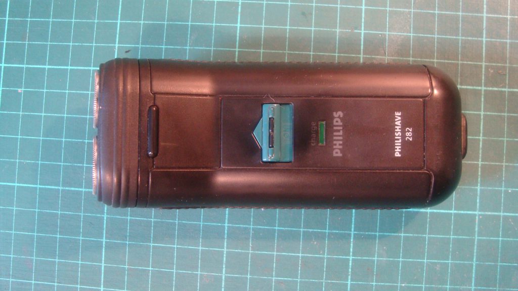
A very old Philishave 282. Still working on mains but won’s hold a charge
Opening the shaver is very easy, using a T8 torx bit, I removed the two screws and the cover can then be carefully removed.
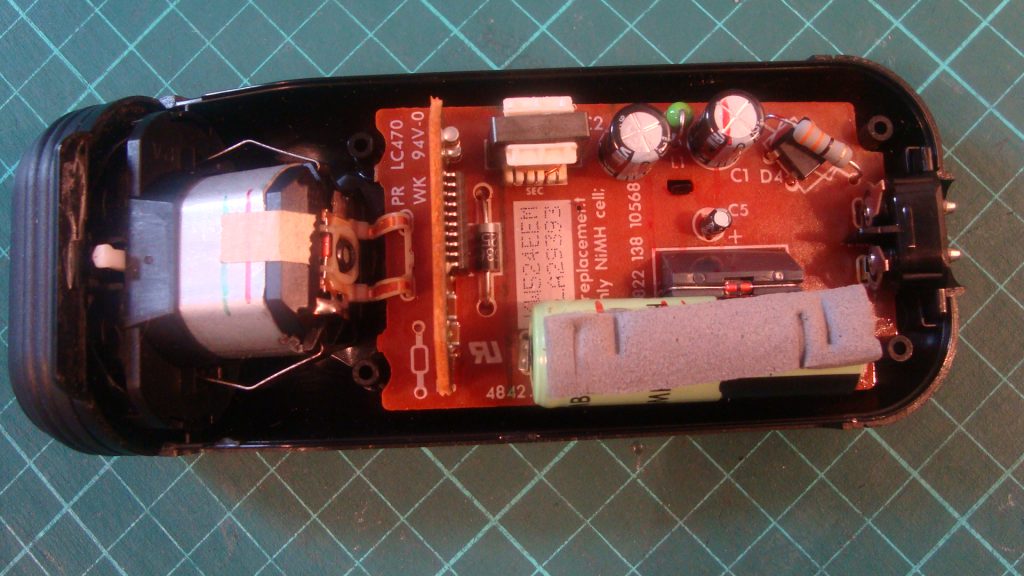
The old battery needs to be removed by lifting out the circuit board and desoldering from underneath.
The circuit board and motor assembley are in one piece. You have to lift them out together to avoid damaging the fine copper cable holding them together.
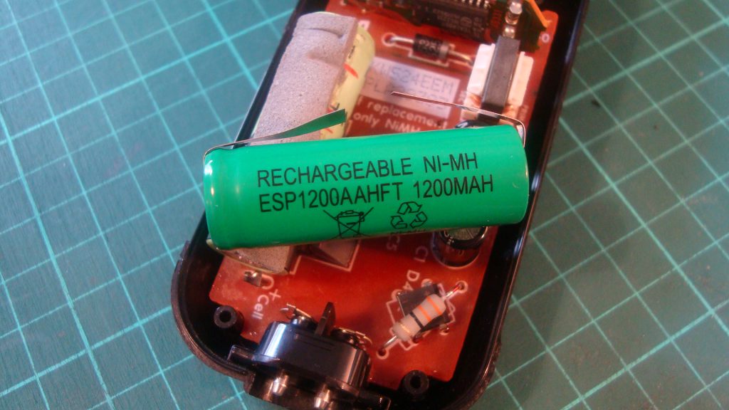
A replacement 42mm x 14mm Ni-MH battery
The new battery cost me £8.95 which was cheaper than the £20 – £25 price of a new shaver.
Here is the video from this morning. I hope you find it useful.
In the video, the old battery is in the wrong way, this is because I have already removed it to check for any identification numbers before ordering the replacement. This makes it look that I have installed the new battery the wrong way around, but I haven’t. I had to double check and admit, I confused myself, until I remembered I had already taken out the old one and must have put it back the wrong way without thinking.
If you have any interest in repairing laptop motherboards, you have likely spent many hours watching videos on Youtube. Here the experts with years of experience, are quickly showing how it’s done, with little explanation of what’s really happening.
For the beginner (like me) this can be both fascinating and frustrating. The lack of information aimed at people just starting out, coupled with a steep learning curve is daunting.
Power rails and buck convertors – the penny drops
But, if you watch enough videos the penny drops and things slowly become a little clearer.
Videos on two repair channels really helped me understand why Loius Rossman keeps mentioning PPBUS_G3 HOT in his Macbook repair videos and how buck regulators.
But what do you do if you want to poke around a motherboard without risking your own laptop?
Well I found a great example of power rails and buck convertors inside a Virgin Media Superhub 2.
If you’re in the UK there’s a good chance you have one laying around after you have upgraded, or know someone who has an old one hiding in a cupboard.
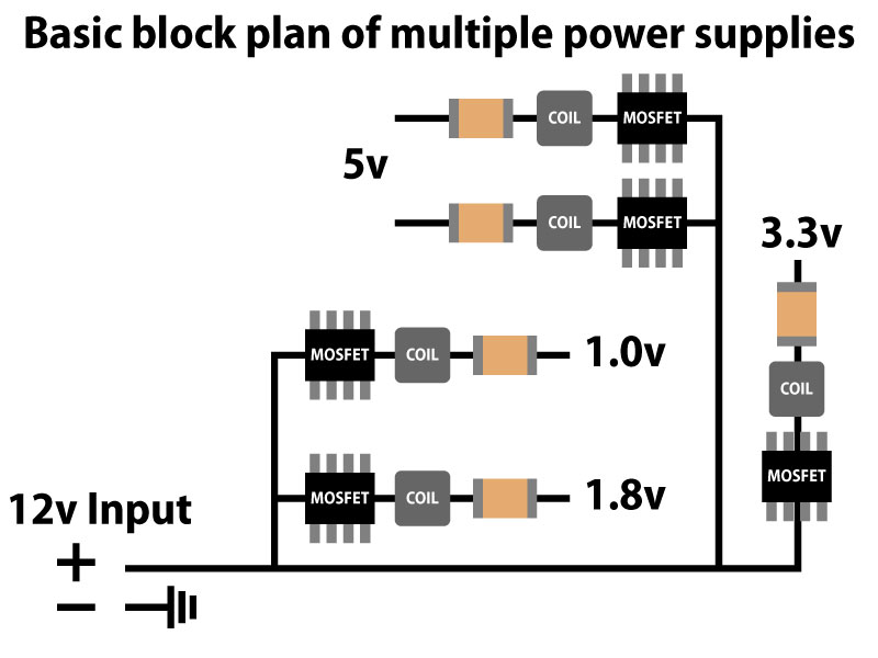
Here is a very simplified view of the power rails.
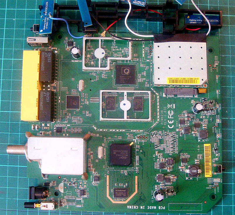
Motherboard or Virgin Media’s Superhub 2
Power rails 1.0v, 1.8v, 3.3v and 5v can be found bottom right
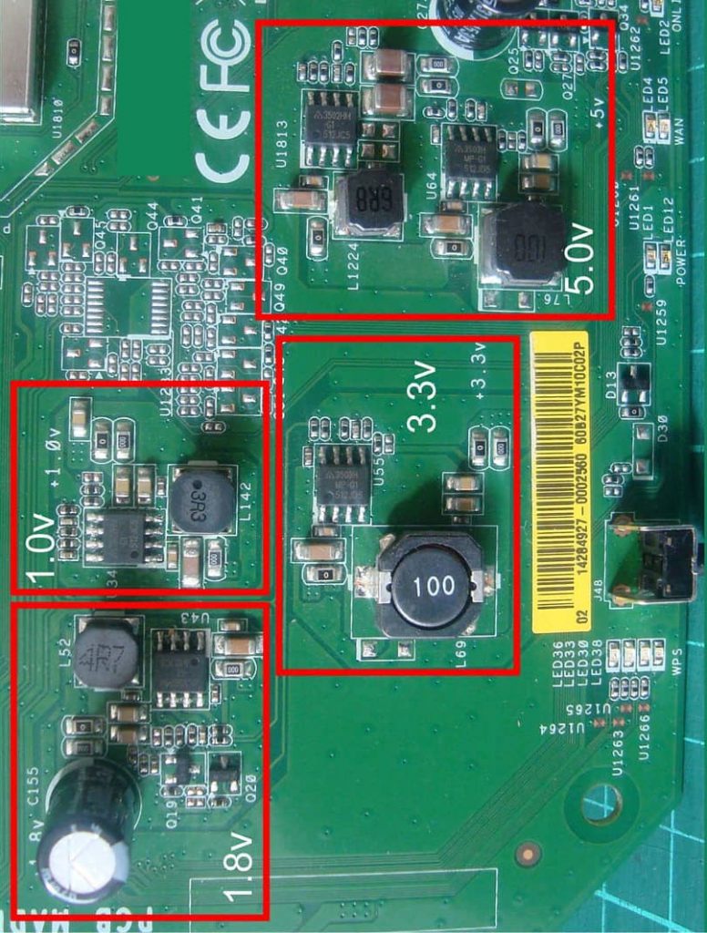
All of the power rails are clearly labelled with their respective output volts, 1.0v, 1.8v, 3.3v, and 5v.
Power rails are clearly labelled
With the help of a multimeter you can explore the board from the 12v supply and probe the inputs and outputs of the various supplies to help get a better understanding of how things work.
The benefit of using a working one, is that you can see how they are supposed to work, rather than blindly probing a dead laptop motherboard, wondering if what you meter reading is correct or not.
Well I hope you found this post useful and good luck with your fixing.
Chips on the board include…
Winbond W971GG6KB-25 1GB DDR2 Memory requires the 1.8v power rail.
E523TH52 DNCE2530GU Intel Puma CPU – I can’t find the voltage or the datasheet for this chip.
This morning I recorded my first ‘fix it’ video when attempted to repair a faulty power jack on a Bush Dab radio.
The radio was donated to me, after the previous owner had tried and was unsuccessful to find a lasting solution.
Expecting it be a dry solder joint, my first plan to re-flow the solder, ended with snapped wires and lots of time lost removing old glue holding the power jack in place.
Watch the video below to find out what I should have done first.
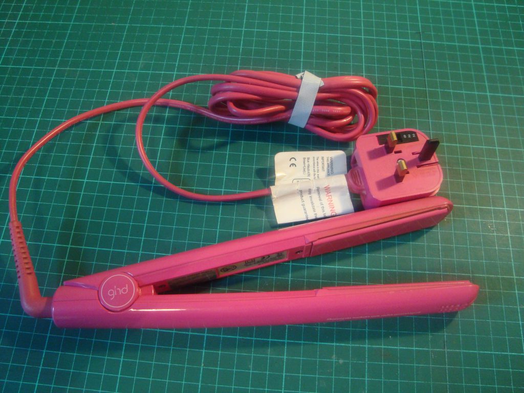
Apparently GHDs are a girl’s best friend, so when my girlfriends pair developed a fault, I had the chance to earn some brownie points, if I could fix them.
GHD 4.2P
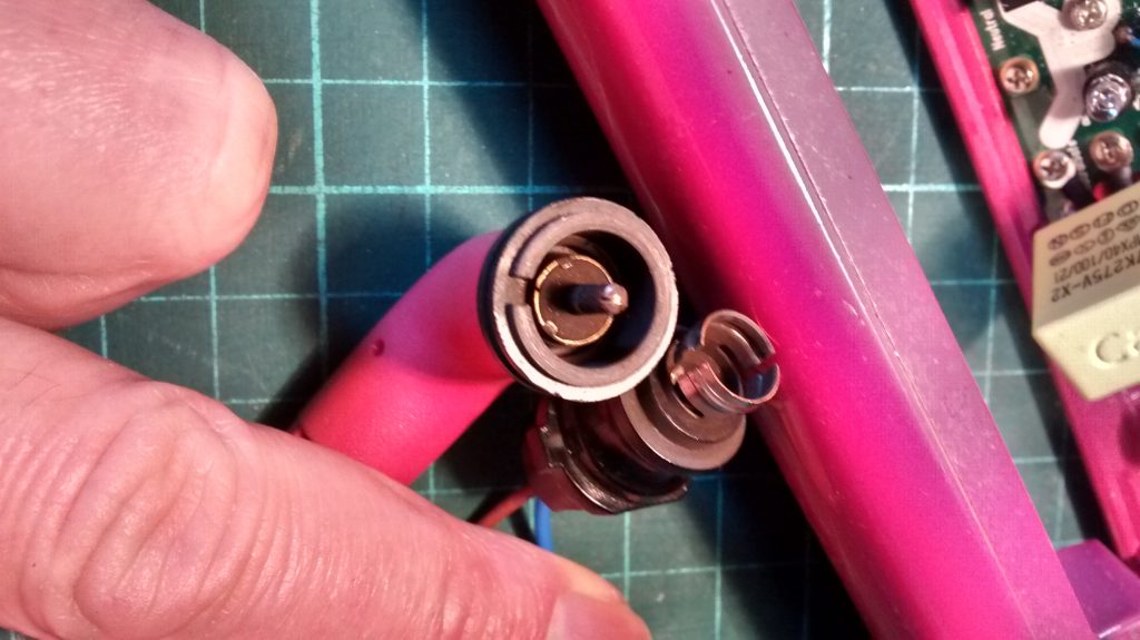
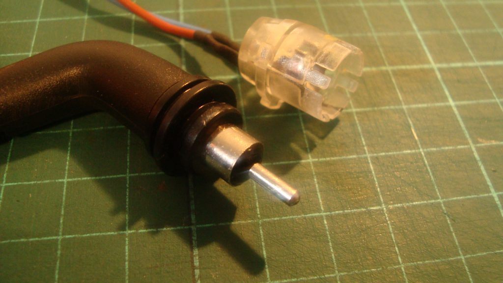
One main problem with ealry 4.2 models is the swivel connector. It’s poorly designed, so if you have a pair that is crackling and popping, then you probably have an old model and you should have the cable and socket upgraded.
Old mains cable and socket on early GHD 4.2 needs upgradingNew upgraded swivel mains adapter and socket
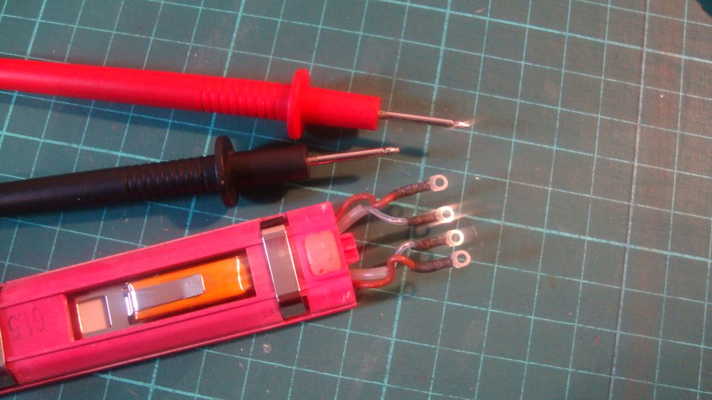
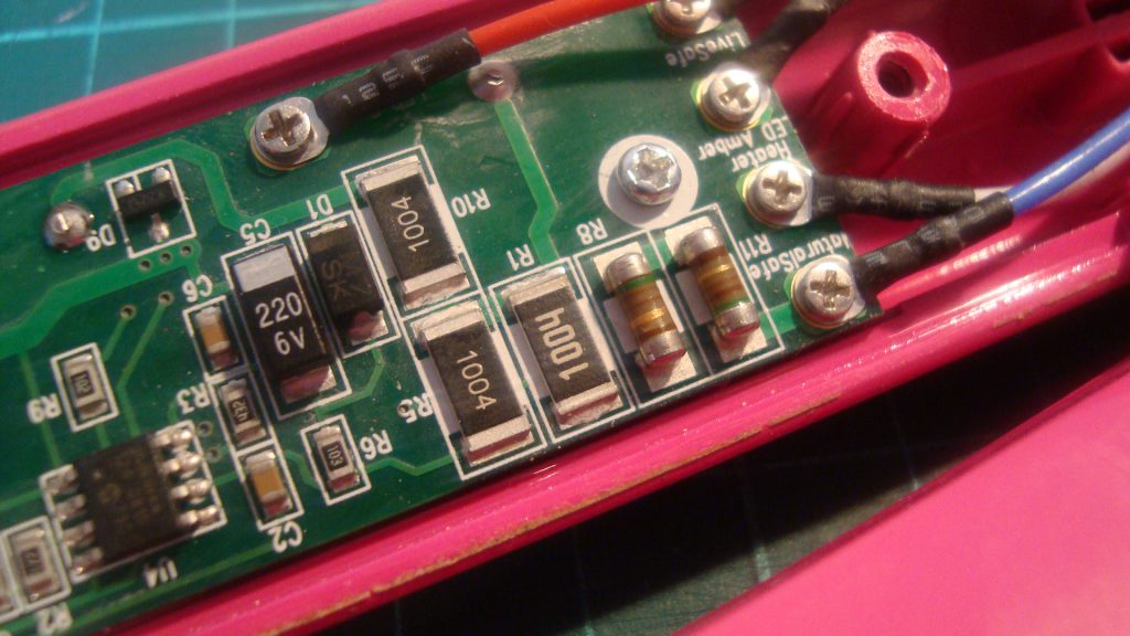
Another simple fix is either replacing the temperature fuse and / or the heating elements. I tested both using a multimeter, the fuse (brown wires) showed it had continuity and the element (clear wires) gave a reading of around 60 Ohms.
Continuity and resistence testing the fuse and element
With the fuse and both elements checked, I moved onto the R11 and R8 resistors. R8 was working but R11 didn’t give any reading.
R11 and R8 resistors
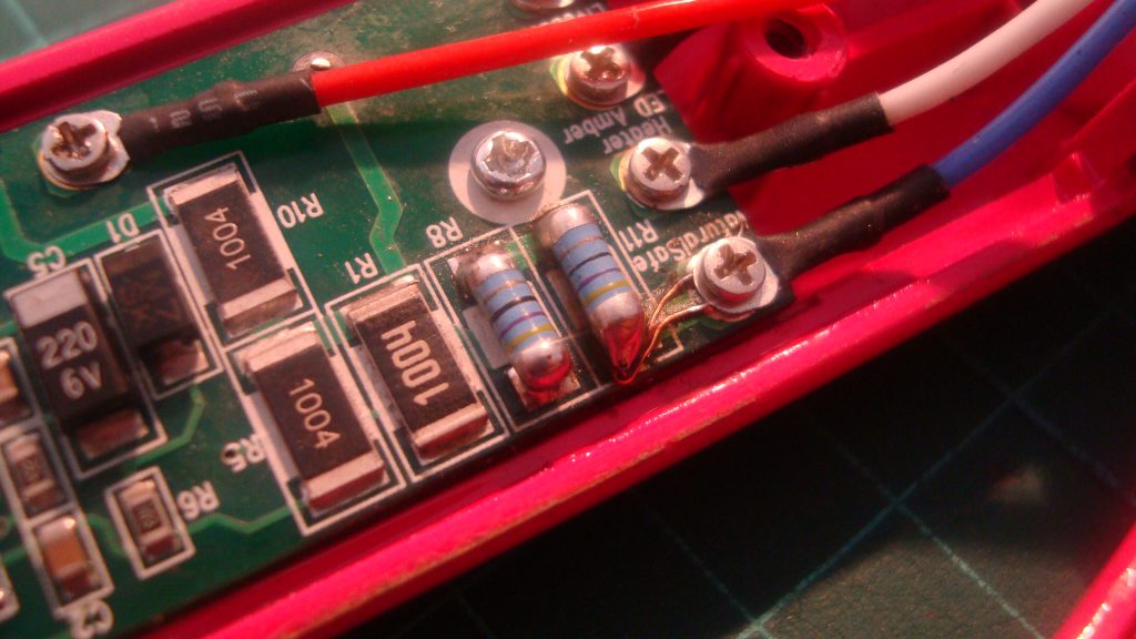
I choose to replace both resistors with new ‘Melf Resistor 50/47 Ohm’.
Sadly it didn’t go as planned and I burnt off one of the pads. Luckily it was pad closest to the screw terminal, so it was a simple case of creating a small jumper wire from the screw terminal to the resistor.
New melf 50/47Ohms resistors with small jumper wire
Success. With the new mains cable and resistors the GHD straighters are working.
The mains cable cost £11.49 and the resistors were £1.99 for 10. When you consider a new pair of GHDs are priced at over £100, spending less than £15 to attempt a fix has been well worth the effort.
Having watched multiple youtube videos of people successfully repairing old and broken power tools, I decided to give it a go myself.
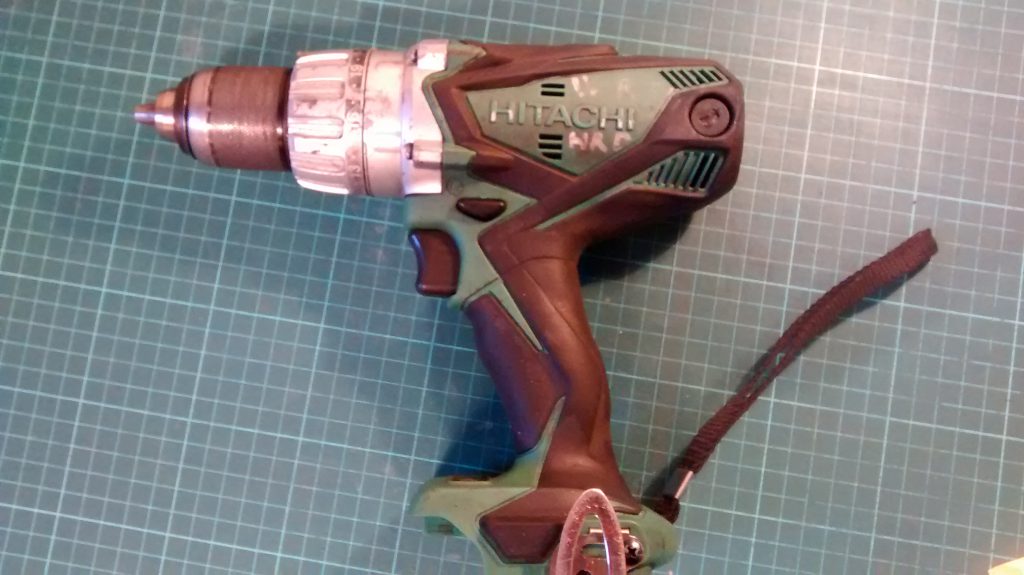
Because I wanted an 18V drill driver for myself I went to ebay and picked up a faulty Hitachi DV-18DSDL for £20.
An initial inspection found no brushes were fitted. Could it be a simple case of fitting new brushed and having a working drill?
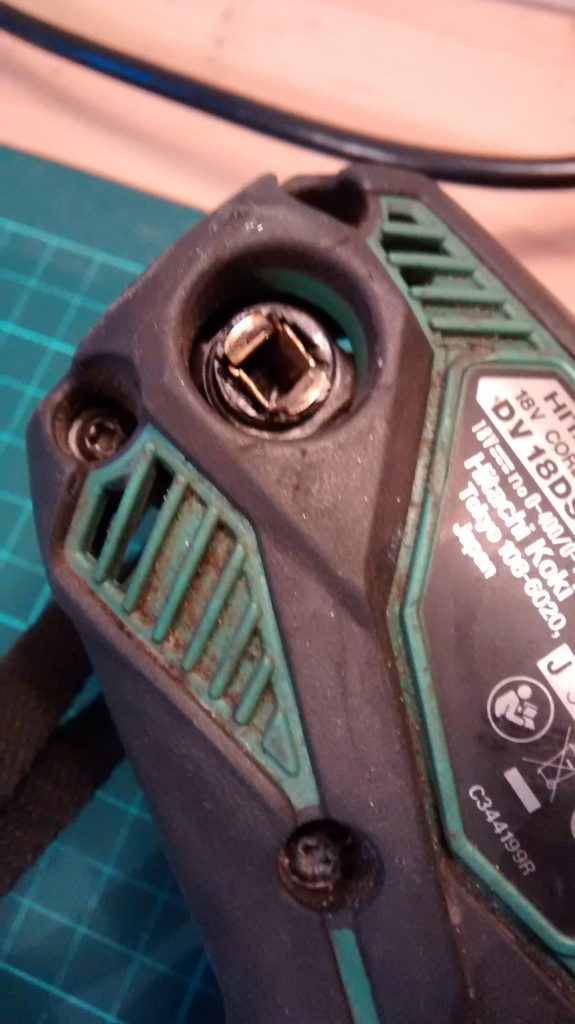
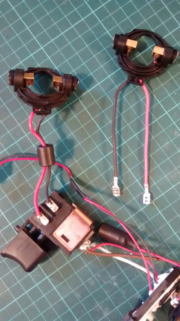
Sadly no. Trying to fit new brushes into the old brush house resulted in a broken brush. So the next option was to order a new brush housing, which came with brushes and brush covers too.
Soldering on the new brush holder wasn’t a problem, but I did notice the red/black wires were on the opposite sides on the new one.
I ignored the colours and kept the brushes on the original side of the switch connector. Had I swapped them over, the forward switch would have ran the drill in reverse and vice versa.
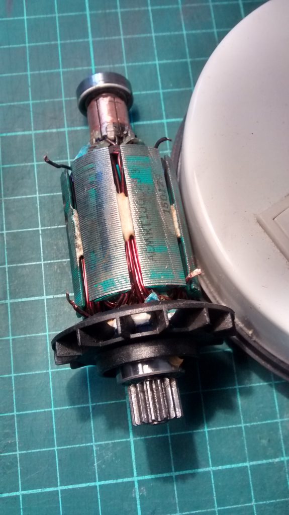
With a new brush holder and brushes, the drill still refused to work, so I turned to youtube and looked at how to fault find the armature.
Using a multi meter and bit knowledge, I found the armature had two broken circuits. This happens when the copper wires have snapped.
Buying a replacement costs around £40, which isn’t economical, so the drill will have to be put to one side and perhaps used for spares, or split up and sold on as parts.
Another option is remove the copper windings and rewind it. I plan to do this when I come across an old motor with the correct sized wire.
Lessons learnt.
Check the armature first, before paying out for any other replacement faulty parts.
This is a series of posts where I’ll be stripping down and cleaning an Helvetia gents watch.
Being my first attempt at horology, I don’t expect things to go straight forward but let’s give it a go.
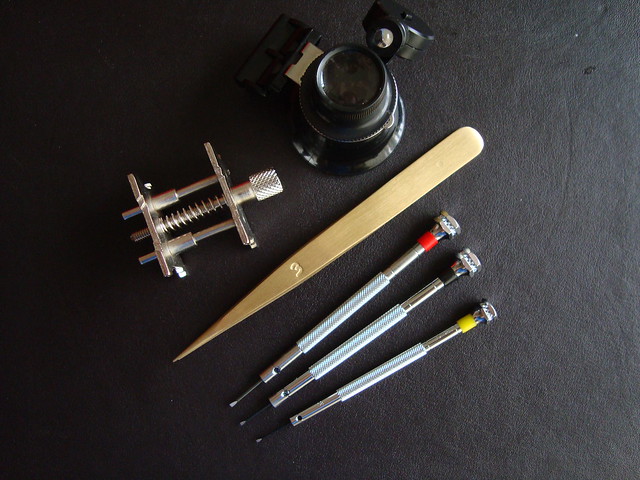
Here are the tools i’ll be using for the project.
Basic watch movement holder
loupe
brass tweezers
0.8mm, 1mm, 1.2mm precision screwdrivers
Step 1 sees the movement removed from the case, there’s normally small hole to release the winder (crown), the pointers are removed next and finally the watch face itself. You’re left with the movement, ready to be dismantled.