This post is for the compete beginner with an interest in the ESP8266 microcontroller. Specifically the plain standard board ESP8266-03.
Let’s start with a disclaimer. I’m a completer beginner too. I have no microcontroller experience, never owned an Arduino, or used any kind of development board in the past. So, don’t take this post as an how-to guide, as I may not be following ‘best practises’. I provide this information as I have done it, and take no responsibility if something goes wrong.
What I’ll cover today, and what I won’t
I won’t cover what the board can do, I will assume you have already done your homework and decided you want to get the board set up and programmed with something simple to get started.
Here are steps this post will cover.
- Set up the correct wires on a TTL USB adapter.
- Solder some pins onto the ESP8266-03 connectors which will allow it to be plugged into a breadboard.
- Install a push button switch on the breadboard (allows the ESP8266-03 to start up in program mode later).
- Install an LED and 1K resistor on pin GPIO 12.
- Set up Arduino IDE and install the ESP8266 board manager.
- Boot the ESP8266-03 in program mode, load the sketch, reboot the ESP in normal mode to run the sketch.
On the software side we will use the Arduino IDE (which is free), to send a program (Arduino calls them ‘sketches’ to the board), which will flash the LED and display text to the serial console in the Arduino IDE.
Step One: Set up the correct wires on a TTL USB adapter.
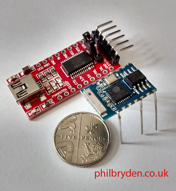
To connect the standard ESP8266-03 board to a PC, you will need a TTL USB adapter. The one I bought is ‘Yizhet 2x FT232RL USB to TTL Serial Converter Adapter 3.3V 5.5V Module Mini Port for Arduino and Raspberry Pi‘ from Amazon.
Make sure it has: RX, TX, 3.3V out and GND. These are the pins we’ll be connecting to the ESP8266-03 module and the breadboard.
I soldered four wires to the pins RX, TX, 3.3v VCC and GND. The soldered connectors are prevented from shorting between each other with some (poorly applied) heat-shrink tubing. RX goes to TXD, TX goes RXD on the ESP8266 and I connected the 3.3v and GND to the power rails on the side of the breadboard.
Step Two. Solder some pins onto the ESP8266-03 connectors which will allow it to be plugged into a breadboard.
Identify the input / output / power connectors needed and solder on some connector pins. If you aren’t using a breadboard perhaps you can just solder on some fine wires. I found some connector pins on an old DVD circuit board, but you could probably cut some legs from a few LEDs.
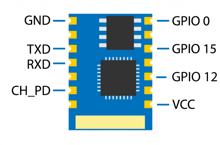
GND goes to ‘-‘ on the breadboard
TXD goes to the RX pin on the TTL USB adapter
RXD goes to the TX pin on the TTL USB adapter
CH-PD goes to ‘+’ on the breadboard
GPIO 0 goes to a push button, which goes to ‘-‘ on the breadboard
GPIO 12 goes to an LED to 1K resistor, which goes to ‘-‘ on the breadboard
GPIO 15 goes to ‘-‘ on the breadboard
VCC goes to ‘+’ on the breadboard
Step Three. Install a push button switch on the breadboard
Now this is where I initially had trouble. To be able to send sketches from the Arduino IDE, you have to boot the ESP8266 into program mode. You do this by shorting pin GPIO 0 to ground while powering it up. I’ve used a push button on my breadboard, but you can leave it off and just use a simple jumper wire from the pin to the ‘-‘ rail on the breadboard.
So when i want to load a new sketch, with the board off, I hold down the push button (which shorts pin GPIO 0 to GND), then plug in the USB cable, wait a moment and release the push button. The board is now in program mode. I can load the sketch using the Arduino IDE.
When the sketch has been installed, I pull out the USB cable to remove power. Then plug the USB cable back in, to switch the board back on, into normal mode, and the sketch will start running automatically.
Step Four. Install an LED and 1K resistor on pin GPIO 12.
To see the output connect an LED to GPIO12, then use a 1K resistor to GND. The code in the sketch will turn on the LED and read the status of GPIO 12 and print the output to the Arduino IDE serial monitor.
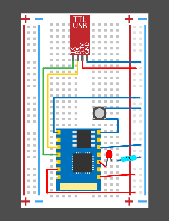
Here is a plan of the layout.
Step Five. Set up Arduino IDE and install the ESP2866 board manager.
Head over to https://www.arduino.cc/en/main/software and install the correct for your operating system.
Once installed go to File/Preferences and pasts this URL where it says ‘Additinal Boards Manager URL’s’.
http://arduino.esp8266.com/stable/package_esp8266com_index.jsonHead to Tools/Boards manager and search for 8266, and install the ESP8266 by ESP8266 Community. From the list of boards you should now select ‘Generic ESP8266 Module’.
Step Six. Boot the ESP8266-03 in program mode, load the sketch, reboot the ESP8266-03 in normal mode to run the sketch.
Blink is basic sketch that comes with the Arduino IDE. The original version of the ESP8266 had a built in blue LED. Because we’re using version 3, there’s no LED, so I have wrote my own code to use GPIO 12 instead.
/*
  Turns an LED connected to GPIO12 on for one second, then off for one second, repeatedly.

  Reads the status of pin GPIO12 and outputs status to the Serial Monitor.

  This code is inspired by the BLINK sketch which is unsuitable for ESP8266-03 because it lack a built in LED.

  by Phil Bryden

  http://www.philbryden.co.uk
*/

// the setup function runs once when you press reset or power the board
void setup() {

  pinMode(12, OUTPUT);  // initialize digital pin GPIO12 as an output.
  Serial.begin(115200); // initialize serial monitor.
}

// the loop function runs over and over again forever
void loop() {

  digitalWrite(12, HIGH);              // turn the LED on (HIGH is the voltage level)
  Serial.println(digitalRead(12));     // Reads the out put of GPIO12 and displays it in the serial monitor
  delay(1000);                       // wait for a second


  digitalWrite(12, LOW);             // turn the LED off by making the voltage LOW
  Serial.println(digitalRead(12));   //Reads the out put of GPIO12 and displays it in the serial monitor
  delay(1000);                      // wait for a second
}
To install this code
Paste the code above into a new sketch in the Arduino IDE
Hold the push button down, while plugging in the USB
Release the pushbutton (the board is in program mode)
Click the upload arrow icon (top left) in Arduino IDE
Wait for the code to be installed (mine displays ‘Hard resetting via the RTS pin…’ when done)
Unplug and plug in the the USB cable (without holding the push button down) to restart the ESP8266-03
The board should now be in normal mode and the code will run automatically.
If all has gone well the LED will blink on and off for 1 second. There should also a print of what is happening in the Tools/ Serial Monitor window, 1 is high and 0 is low.
If the output in the Serial Monitor is garbage, make sure the baud rate is set to 115200 and be sure to check to see that the correct COM port has been selected too.
That’s it, a beginners guide to setting up the ESP8266-03 with the ArduinoIDE.
I hope this has taken some of the confusion I felt when researching this little microcontroller. Most of the information available was aimed at people with development boards, and I found the learning curve quite steep.
What’s Next?
If this post has been helpful, let me know and I’ll follow it up with a post on how to get the board to read a switch input, then turn on the LED.
Good luck with your own microcontrollers and projects.
I have an instagram account with this sketch running and the follow up program where the LED activates when a button is pressed an input pin. Take a look.